Anglia Polytechnic University
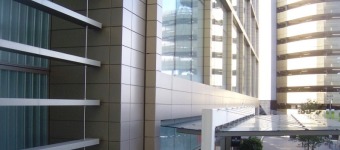
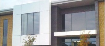
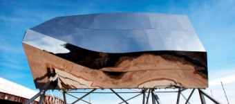
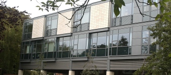
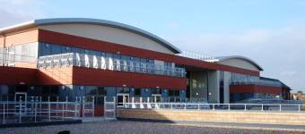
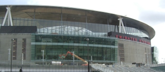
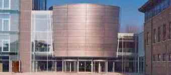
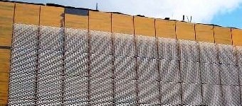
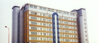
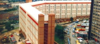
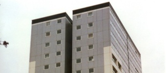
At first glance you could be forgiven for thinking that this is a fairly normal cladding job. Alas no, well actually Yippee no (because we at Rapide Technical Services are crazy enough to enjoy this sort of challenge).
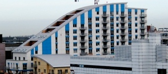
Imagine a cylinder of ø150m that you tilt at 5° and then ram into the ground. (Draw the ellipse on a piece of paper.) Take another tilted 5° in the opposite direction such that it overlaps the first by say 30m. Now take 2 more cylinders ø125m tilted at 10° and ram them in similarly opposite each other at 90° to the first two. The shape described by the intersection of the 4 cylinders is the shape of the building. The roof curves at a radius of 250m, from a point 230m below ground and 50m to the right, front to back and at a radius of 80m, from a point 60m below the ground, left to right.
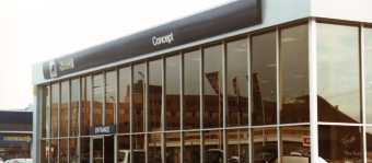
The capping makes for interesting compound curves - try it! Then add a requirement for all the cladding joints to be truly horizontal, bring in adjacent walls & structure, curtain walling at various angles and then allow the facade to proceed below the adjacent roof to become an internal wall cladding. Not quite what you read when you first look at the photo is it?
For the final twist, this wasn't modelled in 3D CAD. RTS Design produced the building shape and all of the components (including flattening the panels to get the profiles needed to produce truly horizontal joints) using 2D CAD and some good old fashioned trigonometry.
Next time - if you have something like this for us to develop for you - we'll use 3D Modelling - we've learnt our lesson.


